Wodaplug EOC Master and Slave
Adapters Wodaplug EOC – Ethernet Data over coaxial networks
PRACTICAL EXPERIENCES AND HOW TO USE WODAPLUG EOC MASTER AND SLAVE DEVICES IN COAXIAL TV OR SAT NETWORKS – SOLUTIONS FOR PROBLEMATIC SITUATIONS
COAX CABLE LINK ATTENUATION
When you use the EOC Wodaplug Master and Slave units, it is necessary to have coaxial lines in good conditions. For TV signal transmitted in band above the 85MHz may be all well and good, but it doesn’t have to be same for range 2-65MHz.
On the route to the Slave there is always some attenuation on the main coaxial cable, but also passive elements such as hubs, splitters, connectors. The hubs is nessesary to calculate with the weakening in 3.5-4dB for 2-way splitter, 3-directional attenuation has a 5.5-series 6 d, 4 directional around 8dB, 6-directional approx. 12dB. turners have an intermediate direction of attenuation, attenuation is by the type of splitter around 1dB.
I tis nessesary to realize, that this kind of attenuation is between input and output. Lets pretend – If we would connect master unit likewise oposite direction, direction to input there will bet he same attenuation , but towards another output this very same attenuation will be much higher, during the manufacturer datas, it will be around 25-30 dB. It means, that if we would like to inject master unit somewhere located in middle of network architecture and not on its begining (ofcoarse not over build in diplex module, but over whole splitter) , there will be in one direction attenuation for example thru double splitter apr 4dB, but for passing part of the network it will get as much as around 30 dB.
Becoase of that, if we want to use master unit to higher distance, where every degree of attenuation counts, is very very important to find perfect spot for master unit placement injectment, ussually best possible is near or next to group station, optical reciever (see our other optical products or our already connected willage sample), or simply source of the signal.
The difference in temperature, also causes differend attenuation shown by master unit in the summer and another in the winter. For this you need to remember, especially if it is some sort of Slave to the edge of the parameters in the winter, it can be assumed the problem with arise in warmer weather, therefore,to avoid this as much as possible, enhance the route parameters.
The values indicated in the management of wodaplug master through a Web interface are very helpful, although they are not completely accurate, they help create a picture of the quality of the network and its individual segments.
CONNECTORS – RUST IS BLAST
A very important part of the koaxial network are connectors, or the execution of their Assembly. By The influence of time and meteorological conditions, however, the metal parts of the oxidation layer is generated, which increases the resistance of the structure. What has a very negative impact on the transmission, mainly in TV zone, in which bandwith these devices works as well. From ours many years of experiences, we can state that the situation can be drasticly improved by cleaning every connection, IE. screw out connectors, spray over with a suitable spray eg. Contact 60 and screw back the connector. The parameters of the connection between wodaplug Slave will improve. doing so on whole route between wodaplug master and slaves, it will make a significant improvement in SNR, which ultimately will increase parameters of the network throughput. When outdoor hubs/splitter are well maintained too, it will also help. Always keep in mind !!! Rust is blast for your network.
We had a lot of cases where the wodaplug Master unit showed attenuation around 60dB, and even sometimes wodaplug slave unit was not available, After treatment of the route the parameters of the connection improved so greatly, that downturn was suddenly only 50dB and the Slave unit goes steadily ever after. (it really happend many times in our instalations and not only at kingdoms far far away )
Sometimes when experiencing bad parameters of the network – may help to reduce the output power of master unit, whether using lovering cells or through the Web interface. Sometimes in network may be a weaker place, for example poorly made grounding, network cable (dismantled or badly fitted drawer). This place then causes a strong signal reflections, and then distort the signal and so worsen the parameters across the whole network, which has an impact on the availability and the slave units to communicate.
GALVANIC SEPARATORS
Another of the problems that may emerge, is the formation of various currents flowing thanks to connecting multiple several different groundings, for example. from the various phases of a variety of grounding terminals, grounding … Each grounding unit has a different potential and when they come across such a pack of two, there is rising of the potential for tension between them and current begins to flow between them. It is, however, interference for TV signals within 65MHz and reduce it again the total capacity of the transmission, or it may cause disconnection of slave units from the MASTER unit.
Also the source of such interference can be made by a source of tension, for sample bad adapter, the TV networks are often involved in computers networks today, for example: TV with 3way plug, in this way, there is unwanted conection between grounding from TV network and it colides with grounding from EOC network and we have problem alive. Such interference can often be seen in the main TV picture of the analog signals such as moving vertical strips.
The solution may be galvanic separator, that separates these different groundings or resources. The best prevention is to involve galvanic separator at the start of the tv antenna network (at the entrance to housings), this way you split/separate networks from each housing/area etc., if that doesn’t work, then you have to find the line bringing interference to TV networks and install (after punishing owner of the housing) galvanic separator for this connection. proven by years of experience you may find this type of Polytronu model KTG220F very usefull. if you need to buy this or any work proven type, let us know.
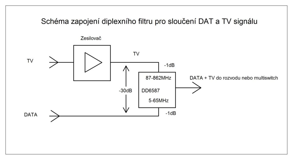
DIPLEX FILTERS
Whereas these data signals spread in TV networks in the 0-65MHz back and forth directions, is necessary to ensure this way goes mainly through the amplifiers. Some of them (especially older nets) have only the active a reverse way, However, it is possible to bypass those amlifiers with pair of diplex amplifiers filters. The input signal to the amplifier plugs into the filter input 0-860MHz diplex, output of diplex 85-860MHz will be connect to input of amlifier, on the other side of this amlifier you connect signal again to diplex 85-860MHz and output from diplex 0-860MHz continue to tv network. In addition, these two diplexes are connected thru inputs 0-65MHz, which in real does so called bypass of the wired signals twoways around that amplifier.
The second option is to Replace amplifier with new with passive back direction 0-65MHz, what may also be a partial improvement of the signal due to the involvement of other connectors and jumpers in bypass.
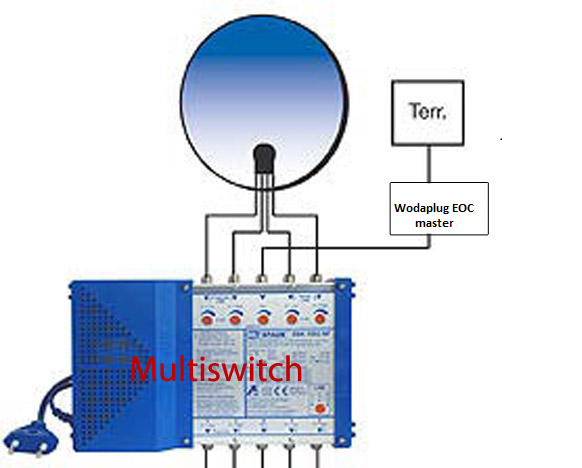
COAX NETWORKS WITH MULTISWITCH
Another option for connecting wodaplug is thru multiswitch – you need to connect Wodaplug eoc master to original terrestrial multiswitch antenna input and multiswitch has to be in passive mode (make sure device is set in passive mode, ussualy its possible only when amplifier is off !!!) – thats what we dont want so often so we come to other possibility.
Amplifying terrestrial signal with wodaplug in network thanks to its build is still possible, but used amplifier has to be connected between Terr. antenna and wodaplug EOC master device to not block data signal injected by Wodaplug EOC master in to Multiswitch. As every plus has its downside, we strongly recommend to lower output power on EOC master unit, in web interface on RF parameters section or using the cell. Try to find best solution to avoid interferences. By our experiences is to lower signal to 112 – 110 dB for medium or bigger networks and 90-92 in smaller networks. At the place of wodaplug slave installation (end customer place – network user) , use ordinary diplex filter, avoid using wodaplug slave as direct coming thru signal in this scenario. You must separate bandwitch with diplex unit up to 67 MHz for slave unit. Please, bear in mind to use some good quality products.
there is even third, ussually best option:
Wodaplug lab offers to ISPs option to bridge your old multiswitch units to make it EOC friendly by inside installing data/bandwith bypassers, we need to know what type it is and other helpfull info before we start . The price starts around 99 Euro per unit and may vary from case to case.
PRACTICAL EXPERIENCE
In practice, there been implemented a number of contracts with these devices on different types of networks and cables. Maximum achieved a distance of up to around 1800m, with the assistance of the use of the transponder/repeater in around the middle of this route, while the main route was on the cable type 860 (these are the ones used on major routes cables -most fat ones :)- ). When you plug in the transponder/repeater means slave and Master, it is necessary to separate the zone 0-65MHz for for those two units, whether by the filter, as well as it is best to engage the input and output of the amplifier, which has turned off reverse way 0-65MHz.
Whereas, however, the larger the trail, the more connections and devices connected to the network, and thus even more sources of interferences by the various reasons described above. Therefore, it is advantageous, as it can be, to make a passage through the optical network (please referr to our optical networks part) and up to its end of the optical node and put the Master connected to the media convertor(please referr to our optical networks part). there are many of networks made this way, and the descibed problems disappeared,with no record of another problems. we split the network to half by this fibre-optic network and thus we achieved a significant reduction in interference in a separate network. wodaplug optic network are very reliable with best possible price.
As regards the number of wodaplug slaves on one wodaplug master unit, We have a networks, where it’s around 30 slave units, some customers have around 60-100. There should be no problem to involve even more of them, including around 120 as indicated by the manufacturer. Much more important is to do so called speed shaping through an external router/server, best suited by brands us Mikrotik , etc. These routers allow you to specify where the speed for each user sets with higher logic with respect to input connectivity. Although the master allows you to set the speed for each of the ports the slave units, however, redistribution is not used as a parameter value of input connectivity and, therefore, the greater the use of capacity to the network may seems sometimes in bigger networks cause stocking the network. The involvement of external router/server, which is managing , the problem disappeared. Of course, if 100% connectivity is used, the only solution is to increase the input connectivity.
A very important parameter, as I have already mentioned, it is, Its SNR It is, therefore, the signal-noise separation which determines the quality of the network for a given point of the network.
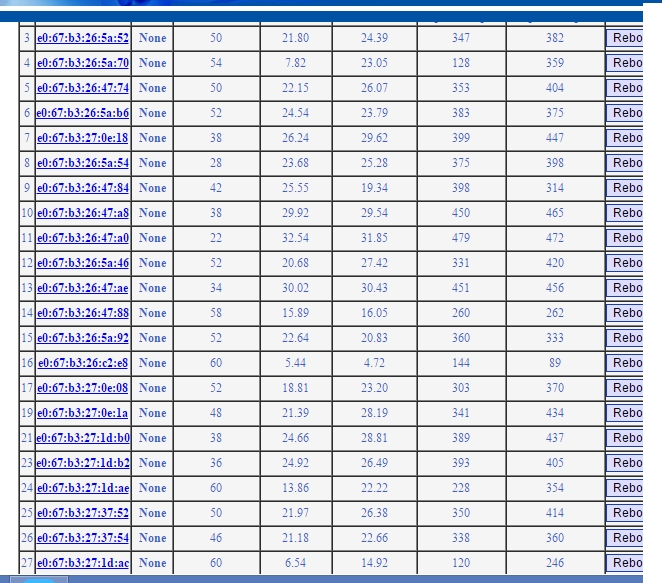
This is a list of wodaplug slaves of the one master, where the connection between the SRN and the attenuation can be seen, in this network we have sometimes blackout only with the slave with the attenuation 60dB and SNR 5,44 and 4.72, but we talking the line in the House, where it goes through the hubs, couplings, connectors, link x it would be quite ok, if better conection can be possible. On the other hand, the slave, the fourth farest from the end has same attenuation 60dB, but the SRN 13,86, and also 22,22, whereas it is involved through less splitters, hubs, connectors, and so it also has a much better parameters speed. It is the most reliable attenuation around up to 50dB, but it works very reliably even at higher attenuation.
Real speed on this network was 100 MB/s, which is in many cases exactly the connectivity, but we have information from one of our customer that it had tested well at much higher speeds in real. It’s mostly about the technical parameters of the network, the device can really achieve the speed specified by the manufacturer is used chipset. Then when we reach over 300 MB/s speed tests.
The reference projects – Ethernet computer network over existing coaxial cable distribution (SAT/TV)
APPARTMENT – INTERNET AND HD IPTV FOR RESIDENTS– WODAPLUG EOC MASTER + SLAVE
Multi-floor apartment house, guest house or hotel with an existing coaxial network needs simply and without additional cables distribute the internet and IPTV to individual apartments – rooms. Thanks to the several floors and the area which makes it dificult to cover it by WiFi signal, to install the HW and also the amount of WiFi accesspoints would significantly burden on the electricity bill. Putting the new cables is not always possible. Therefore, let’s use the coaxial network which is nearly always present either as a common TV antenna (tree) or as a satelite network incoming signal with a hub (star).
Example of use in practice :
Wodaplug EOC Reference – deployment in apartment buildings connected by the optic cable on the internet network and the IPTV for individual entrances through the existing coaxial wiring:
In apartments there are an existing coaxial network systems, whether satellite antennas with combiners or splitters or the common television antennas. Tv technician simply adjusts the active parts in the network for every entrance of the house so it is bi-directionally data-through for band 6-65MHz and after that we connect Wodaplug EOC master to the input combiners / the splitters and then install end units Wodaplug EOC Slave to the individual flats. For each entrance of a residential house is typically one Master to one common coaxial network. The Master unit has the IP address management to setting up the service / VLAN and QOS for individual clients. EOC line acts as a transparent smart Layer2 switch.
Therefore, in the apartment building, which is connected by the fibre optic, We connected master unit via Gbit dac. Further, there has been connected a total of 5 client units in the apartments of the final customers. Into the apartment on the specified VLAN runs IPTV in the form of a multicast. It is tested that the master unit can handle the 4 clients to deliver data for 4 different HD programs in a multicast. The fifth channel on the fifth unit was only SD, therefore a total flow was about 200Mb/s. Every HD program that we ran was moving data around 40-50Mbit/s. at least this flow flowed on one Vlan. At the same time with this multicast TV service still ran internet speed 100Mbit down. For each customer reserved 20Mb on the internet. Therefore, a total of approximately -300Mbit of service. At this load, everything worked and the picture on any channel has’nt made any mistake. But if we’re already turned on a HD program on the fifth slave unit (the other 5-th HD program), It has variously started to err IPTV picture and at different times on a different slave units it began pixeling or scramble. We reached the limit capacity of the EOC line between 300-350Mb/s. Therefore, for using IPTV with HD channels it is applicable for 4 to max 5 Slave units 100Mbit flow reserved for internet. Then the band for the transfer of data is already almost fully taken, it is possible to reduce the reserved part for the internet if you need in one network/the entrance of the house more than 4 customers with the service HD IPTV.
So thats in a nutshell everything about the practical test and deployment with HD IPTV. If it‘s just on the internet, then it’s cool and works even with 20 users and we don’t even know about it.
Connection to the network with splitter and Amplifier – For example 2 apartment houses connected by coax
This is a practical realized example of Wodaplug EOC technologie connection into the existing SAT/TV splitter of 2 neighbor apartment – ilustration of the situation:
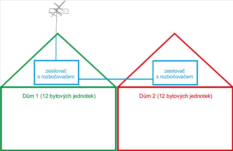
Detail of the previous existing splitter – in house n. 1 is merger with amplifier and with a splitter, in house n. 2 is amplifier and splitter. Then where should we place a data entrance and how we can solve a amplifier pass thru?
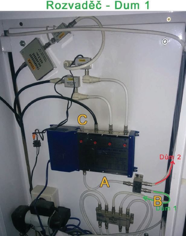
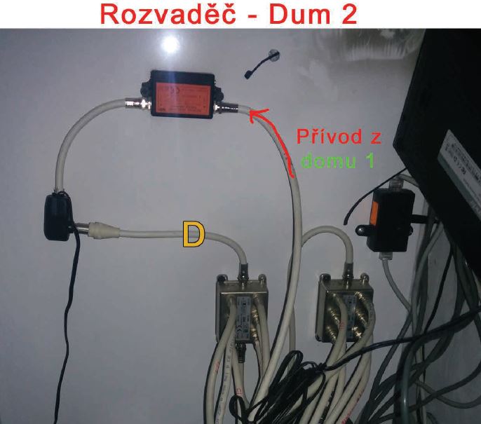
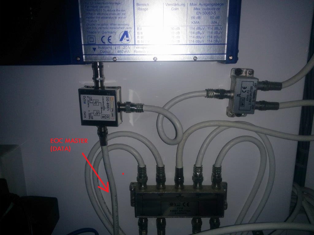
Solution : In a point A in house n.1 connect thru a diplex filtr Wodaplug EOC Master TV and DATA come into the splitter in the house 1 and at the same time into the house 2. At the entrance of the house 2 (in place of the red arrow) insert a diplex filter – input will merge the DATA with TV. Output of the TV plug into the existing amplifier. To the point D connect other diplex filter– TV input into the amplifier output. The merged output of TV and DATA plug into the splitter. All we have left are the two outputs of a DATA on these diplex filters – connect them with the cable and now it start working – so data will go outside of the amplifier – so called bypas.
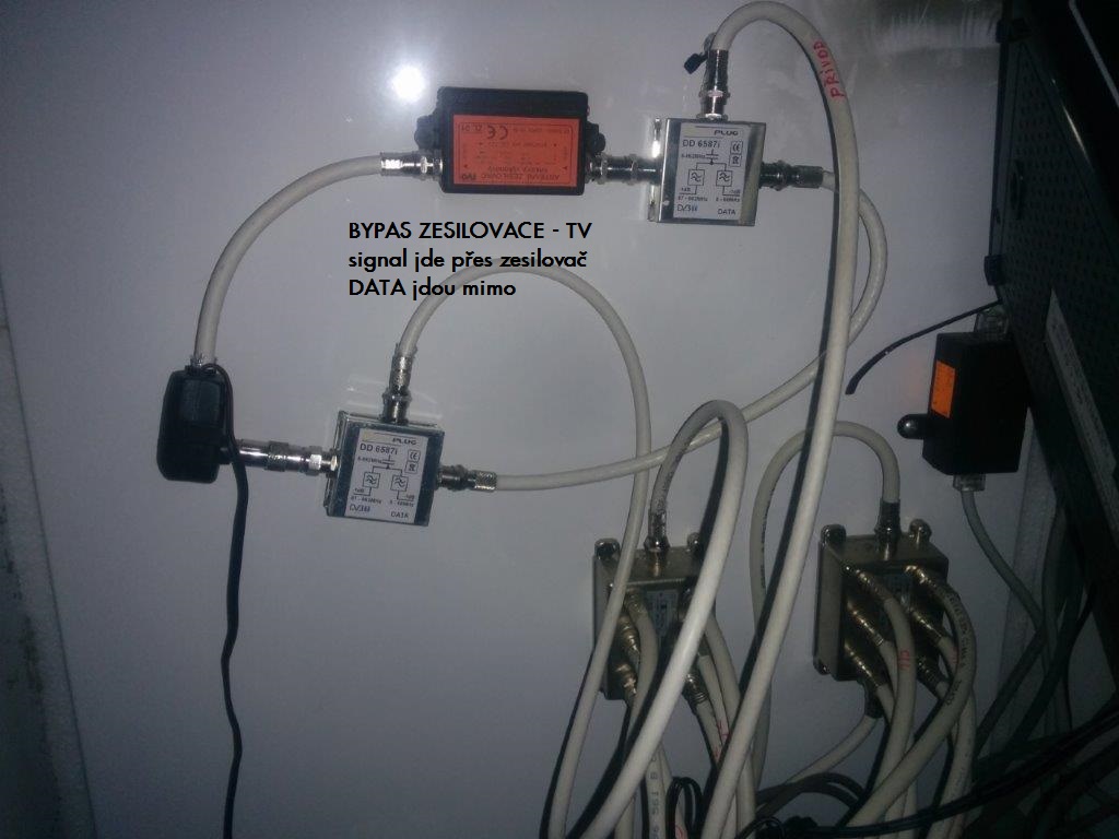
result : TV and data running in both houses! Photo of complete functional connection